
Building a cardioid loop antenna with a Cross Country Wireless Loop Antenna Amplifier + by Chris Moulding G4HYG
Building a cardioid loop antenna with a Cross Country Wireless Loop Antenna Amplifier + by Chris Moulding G4HYG
This web page contains all the information, diagrams and measured radiation polar diagrams to show how to make a cardioid loop antenna with a Cross Country Wireless Loop Antenna Amplifier +.
What is a cardioid loop?...
A conventional loop antenna has a figure of eight pattern with two main lobes opposite each other with two deep nulls at 90 degrees to the main lobes. A cardioid loop has a single main lobe with a high front to back ratio over a wide angle to the rear of the antenna. This allows the cardioid loop antenna to be pointed at a target station to provide a far higher signal to noise ratio than a conventional loop antenna due to the reduced level of noise and inteference received off the back of the antenna.
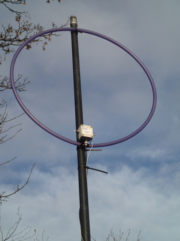
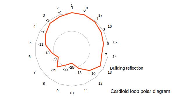
Actual measurements taken with the prototype antenna in the photograph give a -3 dB beamwidth of 110 degrees with a similar angle at the rear of the antenna greater than 15 dB down on the forward direction. A sharp null at the rear of the antenna can be used to null out individual interfering stations on the frequency.
The polar diagram plot shows the measured signal levels from a strong broadcast station within ground wave range on 909 kHz as the antenna is rotated through 360 degrees. Note that there is a small peak at 120 degrees due to the reflection off a metal clad building 20m away from the antenna.
The cardioid loop has directivity up to 8 MHz. Above this the pattern becomes omni-directional.
How do I make it?...
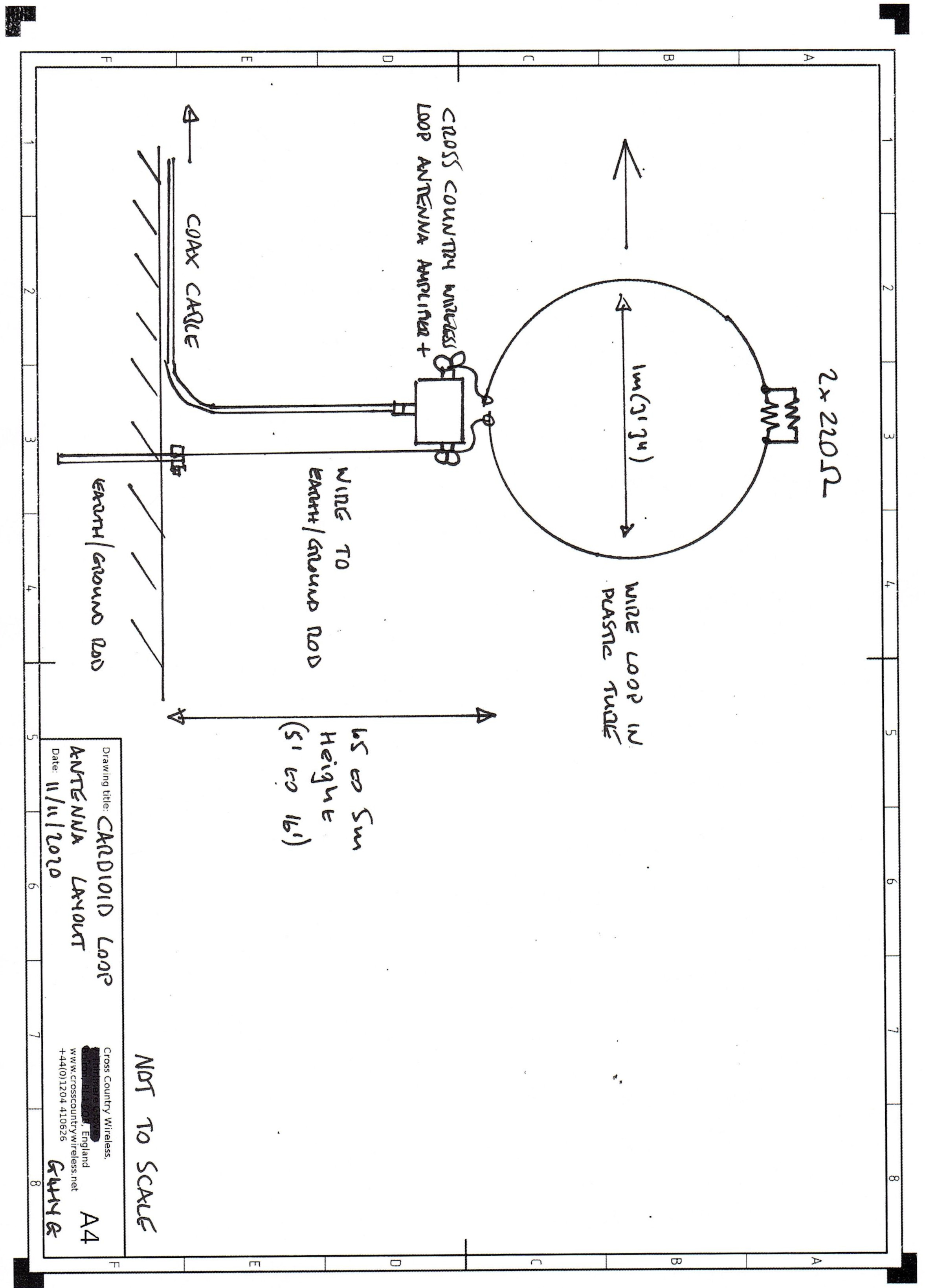
The photograph on the right shows the prototype with a 1m diameter plastic "hula-hoop" to house the loop wire. Directly opposite the amplifier the wire is cut and a 110 ohm resistor is connected in series with the wire. I suggest using two 220 ohm resistors in parallel to make the 110 ohm resistor. The loop is then connected to the Loop Antenna Amplifier + in the usual way.
The loop can be mounted from 1.5 to 6m (5 to 16 feet) high above the ground. A wire is run from one of the Loop Antenna Amplifier + terminals down an insulated support pole to a ground or earth rod buried at the base of the antenna. I suggest using an insulated support pole to give the best front to back performance with the antenna
The coax cable is not connected to the earth or ground wire as this would bypass the common mode choke in the amplifier. The coax cable is run down the insulated support pole and out to the base unit or bias tee unit to the receiver.
You can click on the Cardioid loop antenna layout drawing below for a larger version that will print at full size.
The main lobe is opposite to the loop terminal with the earth/ground wire attached.
How does it work?...
The idea behind the cardioid loop goes back to before World War 2 when loop antennas were used on aircraft for direction finding.
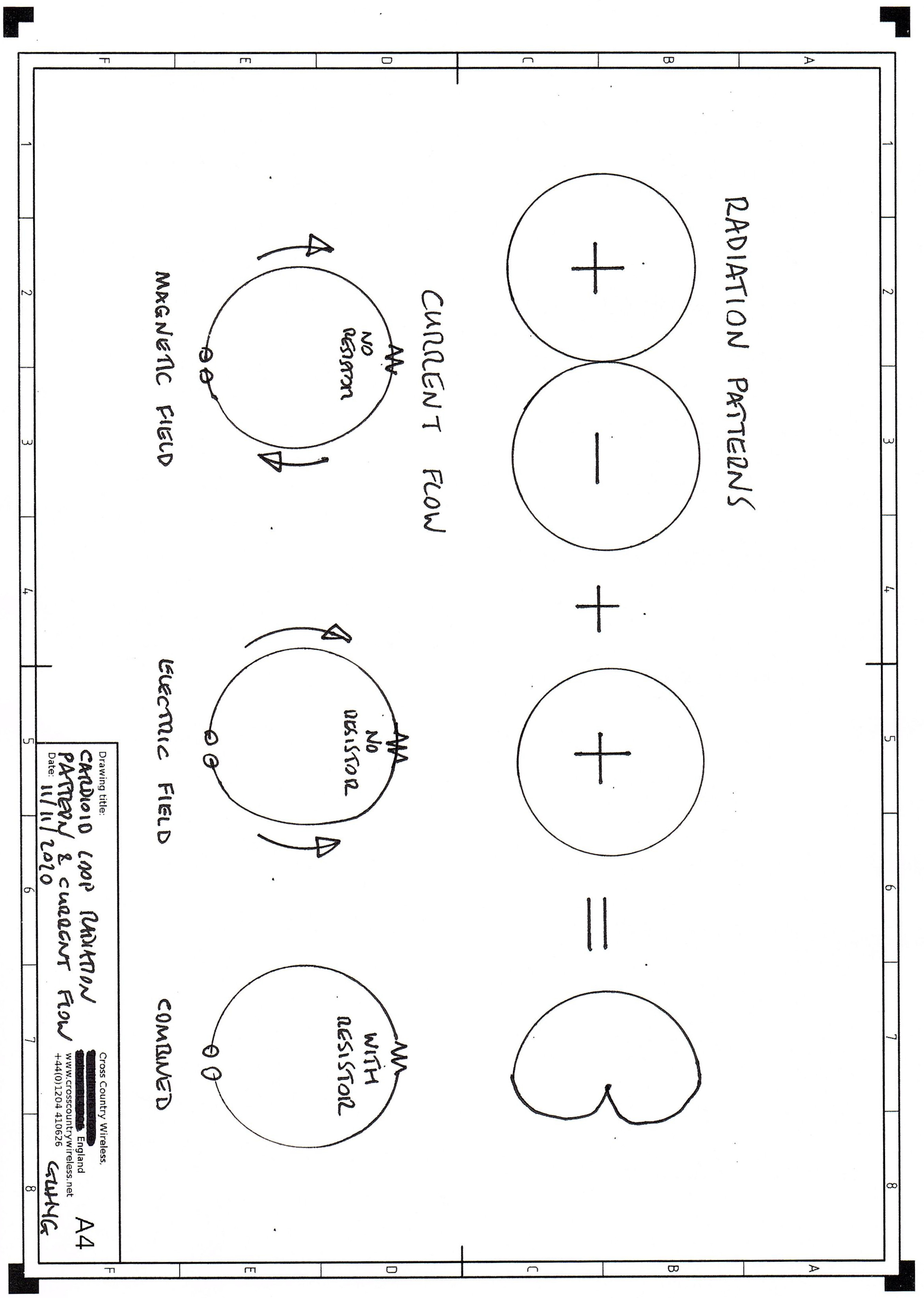
When a vertically polarised loop is used it has a figure of eight azimuth pattern. This would give two possible directions for the target station. Fortunately one of the lobes of the azimuth pattern had a positive polarity and the other had a negative polarity.
To find out which direction was the correct one a vertical whip antenna or "sense" antenna which had a positive polarity was connected to one of the terminals of the loop. This would cancel out the negative polarity lobe and add to the positive polarity lobe giving a form of cardioid pattern that was used to indicate the true direction of the target station.
In 1974 C&S Antennas in the UK refined the idea of a separate loop and sense antenna by combining them into one antenna. Their idea was to insert a resistor in the loop directly opposite the feed point. This still allowed the loop to act as a magnetic loop but also as two monopoles as an electric field antenna. This had exactly the same effect as using separate loop and sense antennas and using modern antenna modelling software can be optimised to give a good cardioid pattern.
It's of interest to note that I came up with exactly the same values they did so the modelling tool they used was probably an earlier version of the NEC 2 tool I used.
How does it perform?...
Very well! It is by far the best loop antenna I have ever made with the Loop Antenna Amplifier +. In operation it is very similar to using a Yagi antenna on a tower on HF. For instance if you were in the UK you could turn it towards the US and all the European stations will drop by two S points or more. If you are in the US you could point it at Europe and all the US stations will drop the same.
If you need to set an antenna up to monitor one specific station or direction then it would be ideal.
The only other antenna that would do that on LF and low HF would be a Beverage antenna. When C&S Antennas released their antenna they sold phased arrays of the cardioid loop antennas to sharpen the main lobe so that it was equivalent to a Beverage antenna without needing the amount of land that the Beverage antenna takes.
Update January 2021...
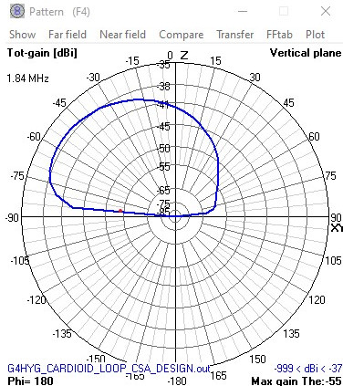
Recently I've been working with Simon Phillips G0ZEN on a larger version of the cardioid loop optimised for 160m and medium wave DXing. This version of the antenna is a square wire loop with 2 m long sides mounted 1 m above the ground. The resistor in the top of the loop is 645 ohms. This has a very high front to back ratio of over 30 dB. The feed impedance of the loop is high so it needs a 9:1 transformer between the loop and the Loop Antenna Amplifier +. The NEC file for use with the 4NEC2 antenna modelling program can be downloaded here.
The NEC file is designed so that the size of the loop (side), height and resistor value can be easily modified in the 4NEC2 editor to suit local operating conditions. The 4NEC2 Optimiser can also be used to calculate the optimum resistor value for best front to back ratio once the loop size and height are determined.
The elevation diagram below gives some idea of it's performance on 160m.
Cross Country Wireless have now released the Beverage Antenna Amplifier. This is ideally suited to the higher (450 ohm) impedance of the larger cardioid loop antenna. A link to the amplifier is here.
Contact Chris Moulding via info@crosscountrywireless.net