
Cross Country Wireless HF Magnetic Loop Antenna...prototype developments
Cross Country Wireless HF Magnetic Loop Antenna...prototype developments
Product discontinued, web page for information only
We've been making the HF Active Loop Antenna for a few years now and whenever we attend radio rallies and hamfests or mention it to other radio amateurs I'm always asked "When are you going to make a transmit version?".
The first thing to note is that there is an awful lot of incorrect and misguided information on the internet about magnetic loop antennas. Since I built the prototype I can understand how that comes about as the resistive losses have to be kept extremely low and it's possible with a small amount of loss (say 0.1 ohm) to have an antenna that appears to work and match correctly but has high RF losses giving misleading results.
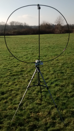
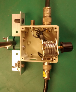
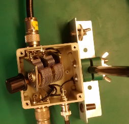
The first prototype uses a 1m diameter loop of S400 (LMR400 equivalent in the UK) with high quality N type male connectors. These fasten to two N type female connectors mounted on one of the polycarbonate boxes used for our existing antennas.
This allowed me to test various feed arrangements and a range of variable capacitors.
 The first capacitor was an Oren Elliot 384 pF single gang variable. This gave very poor results on transmit but appeared to tune and peak perfectly on receive. A DC check showed 0.1 ohms across the capacitor frame and sllding contact to the rotor. This was enough to lose a lot of power on transmit.
The second capacitor was a new old stock Jackson Brothers 365 pF dual gang capacitor. The ends of the loop were connected to the stators allowing the rotor to tune without any RF current flowing through the sliding contact. This was efficient but the maximum power that could be applied was 25W before the capacitor flashed over. I'd like to manufacture an antenna that could take 100W as least.
The supply of the JB capacitors is limited as they are not being manufactured anymore and the Oren Elliot range of capacitors are extremely expensive once they have been shipped to the UK and had tax applied.
 At this point it's worth noting that the magnetic loop antenna is a resonant tuned circuit and the RF voltages across the capacitor and the RF current flowing through the loop should be very high if the losses are low. With 100W on 14 MHz the RF voltage across the capacitor should be 3500 V peak and the RF current in the loop 16.6A. Serious stuff!
There are very few variable capacitor manufacturers left so the choices are very limited and expensive.
At this stage the only option left was to look at manufacturing a capacitor ourselves.
The first prototype capacitor was a compression type capacitor using PTFE sheet as a dielectric. This should be capable of withstanding the high RF voltages and current.
The initial tests of the PTFE capacitor worked well. The tuning bandwidth is sharper than the air spaced capacitors indicating that the losses are lower.
Applying RF power to it there was a dramatic flashover at 80W. After stripping it down the flashover was not across the capacitor but from one of the mounting screws on the N type sockets. The arc had jumped across the air gap to the capacitor plate.
This showed that we were on the right lines and since the first initial test over 50 variations have been tested using different designs of capacitor plate, different surface treatments to the capacitor plates, different thicknesses and makes of PTFE for the dielectric. Good development work is never easy!
Due to the very high RF voltages at resonance it was possible with thin capacitor plates to get a corona breakdown at the edges. Over a period of time this melted the PTFE allowing a flashover to occur. Tests using low duty cycle CW or SSB transmissions wouldn't show these effects so I ran all the tests using 48 second long JT-65 data mode transmissions at a power of 100W.
Finally we have come up with a suitable design that meets the requirements of 100W continuous carrier. It's considerably more robust than a simple theoretical capacitor design would indicate.

Yesterday 24th January 2017 I ran a one hour session on the 20m amateur band using JT-65 to see how this prototype of the magnetic loop antenna performed on-air. It was mounted so that the bottom of the loop was 2m above ground. I started by calling stations then later calling CQ. I worked three stations in Russia, Romania and the Canary Islands and then was called after a CQ by WB7BOW in Washington state. We didn't manage the full QSO but obviously heard each other.
The station in the Canary Islands EA8/YL3AKQ kindly sent a QSL card by eQSL. Interestingly he was using a Ciro Mazzoni Baby Loop so it was a loop to loop contact.
I've included a copy of the PSK Reporter map for the session. The map shows which stations were receiving my transmissions including WB7BOW at 4658 miles, not bad for a 1m loop antenna!
So that's the progress so far. There is a lot of development work to do with tests of 1 and 2m diameter loops using LDF4-50A Helix coax cable using brass studs and lugs to try to reduce the RF losses even more. I've already calculated the ICNIRP RF safety distances for the antenna as 1.5m at 5W and 2.5m at 100 W so a remote control system for capacitor tuning has to be designed to make it safe to use.

The development continued with a remote control tuning system based on an Arduino and heavy duty loop being completed and tested successfully. We have taken the decision NOT to put this antenna into production as the safety clearance distances are unlikely to be observed looking at internet photographs of how other magnetic loop antennas are used by the amateur radio community.
Contact Chris Moulding, G4HYG via info@crosscountrywireless.net
