
Reflectorless yagi antennas with designs, models and plots
Reflectorless yagi antennas with designs, models and plots
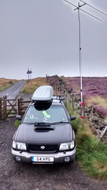 I like to take part in the RSGB UKAC contests every Tuesday evening. Recently I've started operating portable from a location on the approach road to the Winter Hill TV transmitter.
Over the summer I've been tinkering with a 2 element 50 MHz reflectorless yagi design by Martin Steyer, DK7ZB. This a short boom design using a driven element and a director and I found that it gave an excellent performance from home during this year's Sporadic-E season.
I wanted to build a portable version of the antenna that I could take with me in the car. I needed an antenna that was robust enough to stand a bit of rough handling and that could be easily dismantled in the dark at the end of the evening's contest. I decided to use 12mm diameter elements insulated with plastic antenna fittings on a 25mm square boom. This could mount at the top of a 5m Harris painters pole using a 25mm Stauff clamp.
I also wanted to redesign the antenna so that the antenna was optimised for what I wanted to do. Most antenna designs are modeled in free space so that comparisons between different antennas are easy but I wanted to optimise the design for gain and VSWR at 5m over relatively poor ground. I also wanted to use the 25 ohm (2 x 50 ohm cables in parallel) match to 12.5 ohms that I used with the original DK7ZB antenna. I used the 4NEC2 antenna modeler and optimizer tool written by Arie Voors which can be downloaded here.
The NEC file of the 50 MHz 2 element reflectorless yagi can be downloaded here.
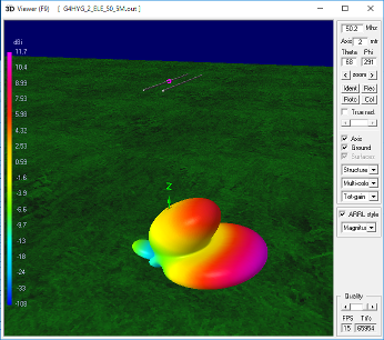
The 3D plot shows a peak forward gain of 11.7 dBi taking ground reflection into account with the main lobe 15 degrees above the horizon. My portable operating position is on a steep hill with a gradient of about 1 in 10 so this will lower the main lobe closer to the horizon.
In use the VSWR was very low as predicted with the 25 ohm quarter wave match and the pattern appeared to match the 3D plot with a good front to back ratio. The relatively large 12mm elements were easier to see in torchlight when stripping down the station.
At this point you are expecting me to say that I won the contest. I'm not that good an operator as I'm half deaf and easily distracted! Let's just say that it's the best result in a 50 MHz contest for me so far and I had a lot of fun. Isn't that what amateur radio is really about?
The 50 MHz antenna dimensions are as follows:
Driven element: 2932mm
Director: 2763mm
Spacing between the elements: 400mm
Element diameter: 12mm (1mm thick tube)
Boom size: 25mm square (1mm thick)
25 ohm match: 2 x 1m RG-174u cables in parallel
I've also designed a 70 MHz version of the antenna.
The NEC file of the 70 MHz 2 element reflectorless yagi can be downloaded here.
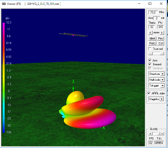
The 70 MHz contest is at the end of the month (September 2015) so no on-air tests yet. The VSWR tests shows that the match is OK.
The 3D plot shows a forward gain of 12.3 dBi (over poor ground) with a main lobe 12 dgrees above the horizon.
On 70 MHz I'll be running the Sentry SDR transceiver prototype so two PCs in the car for logging and operating. What did I say earlier about being easily distracted?
The 70 MHz antenna dimensions are as follows:
Driven element length: 2085mm
Director length: 1960mm
Spacing between the elements: 295mm
Element diameter: 12mm (1mm thick tube)
Boom size: 25mm square (1mm thick)
25 ohm match: 2 x 715mm RG-174u cables in parallel
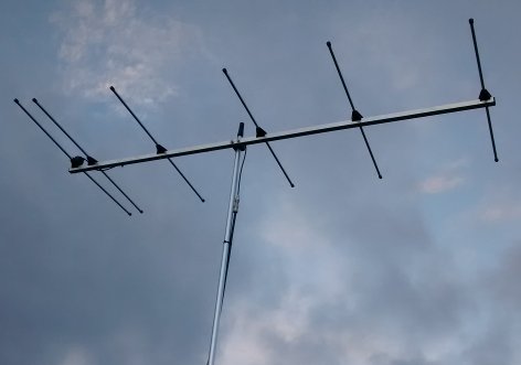
I've already extended the basic 2 element design to 6 elements for 144 MHz operation.
The NEC file of the 144 MHz 6 element reflectorless yagi can be downloaded here.
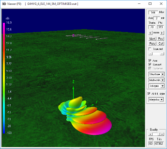
The 3D plot shows a gain of 16.9 dBi over poor ground at 5m high with a main lobe at 6 degrees above the horizon.
In use the VSWR was perfect, no movement on the Bird 43 meter on reflected power with 50W applied to it. The antenna pattern in action on the hill was just like the 3D plot with a lot of gain and good front to back. Again my best performance on 144 MHz so far. I think that designing the antenna to match the conditions of portable operation is turning out to be a good thing to do.
The 144 MHz antenna dimensions are as follows:
Driven element length: 1060mm
Director 1 length: 960mm
Director 2 length: 903mm
Director 3 length: 844mm
Director 4 length: 886mm * see note below
Director 5 length: 829mm
Spacing between the elements:
Driven element: 0mm
Director 1: 95mm from the driven element
Director 2: 475mm from the driven element
Director 3: 985mm from the driven element
Director 4: 1467mm from the driven element
Director 5: 2039mm from the driven element
Element diameter: 12mm (1mm thick tube)
Boom size: 25mm square (1mm thick)
25 ohm match: 2 x 330mm RG-316 cables in parallel
* Note: The length of Director 4 is longer than directors 3 and 5. It's best to label the directors clearly to avoid confusion during assembly.
After successfully making practical working VHF antennas from 4NEC2 computer models my next project is to look at my own home HF station.
I currently use a homebuilt Cobweb antenna on 20, 15 and 10m with a inductively and capacitively loaded element for 30m. The antenna is mounted at 9m above ground again over poor earth due to roads, paths, buildings etc. Would a 2 element reflectorless yagi be an improvement?
I've modeled the cobweb antenna in 4NEC2.
The NEC file of the Cobweb antenna on 14.1 MHz can be downloaded here.
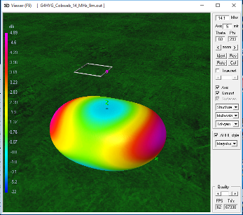
This ties in exactly with what I hear on 14 MHz 20m using the antenna. It's not got the highest gain but it's a reasonable performer and it's better than a vertical antenna with the poor local ground conditions.
It's very quiet on receive and it doesn't pick up much local RF interference. What does the near field model plot show?
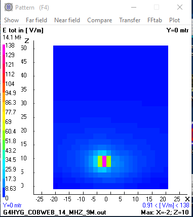
This shows that the electric field around the antenna is very intense but small in area so this probably explains why it doesn't receive much local RF noise.
How would a 2 element reflectorless yagi compare?
The NEC file of the 2 element reflectorless yagi antenna on 14.1 MHz can be downloaded here.

An extra 5.5 dB (nearly 1 S point) in gain over the Cobweb with good front to back and front to side performance.
How does the near field performace compare? Will it be as "quiet" as the Cobweb antenna?
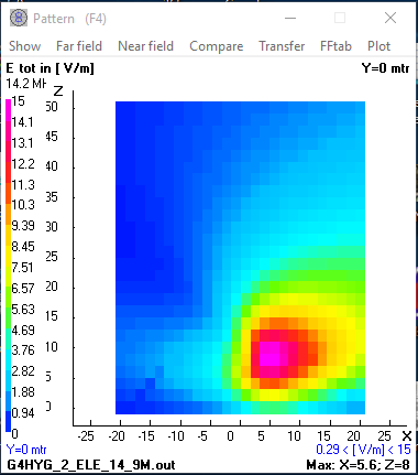
Completely different to the Cobweb design, less intense but the near field covers a greater area. Possibly it may pick up more local RF noise. Will the extra gain and directionality be worth it? Worth a try? Maybe for portable use?
The 14 MHz antenna dimensions are as follows:
Driven element: 10.513m
Director: 10.217m
Spacing between the elements: 1.36m
Element diameter: 1.5mm wire on fibre glass fishing poles
Boom size: TBD
25 ohm match: 2 x 6.633m RG-58u cables in parallel
Back to main Cross Country Wireless web pages
Contact Chris Moulding, G4HYG via Email address hidden from spambots for more details, comments or feedback.