
RF dummy load using wirewound resistors by Chris Moulding, G4HYG
RF dummy load using wirewound resistors by Chris Moulding, G4HYG
 How many times have you been told that you can't use wirewound resistors at RF? Probably many times! On this webpage I show a method to make a resistive termination or dummy load that uses the inductance in wirewound resistors in a lossy low pass filter to extend the frequency range to cover the full HF radio spectrum.
Since I developed the Terminated Inverted U antenna I have had many questions mainly asking where to source a high power 390 or 400 ohm resistor to run the antenna at the legal power limit for amateur radio transmitting of 400W in the UK.
Here at Cross Country Wireless we make a 50 Watt rated 390 ohm resistor unit based on a noninductive thick film resistor. It's possible to buy 100W thick film resistors but the price goes up faster than the power rating.
High quality panel mount wirewound resistors are available at low prices compared to thick film resistors. Was it possible to use them at RF? Conventional wisdom says no...
Testing four Arcol HS50 100 ohm 50 W wirewound resistors in series on our HP network analyser showed that the inductance affected the required impedance match at higher frequencies as expected. Using the resistors in series on their own the impedance match was OK up to 4 MHz but became too inductive above that.
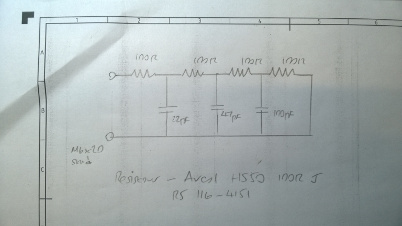
I calculated that if I added capacitance to ground from the resistor junctions it was possible include the inductance of the wirewound resistors as components of a low pass filter. The final values shown in the schematic diagram were proved after calculation and test.
The circuit uses the inductance in the resistors and the capacitors as a low pass filter with a cutoff frequency around 30 MHz. This allows RF power up to 30 MHz to flow through the resistors and be dissipated as heat.
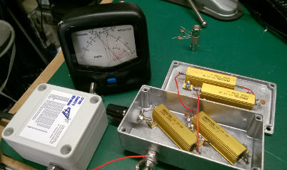
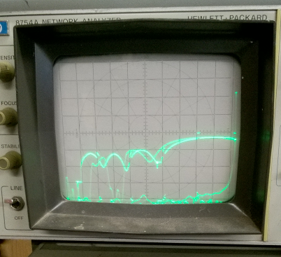
The impedance match of the resistor low pass filter measured on a HP network analser is OK up to 30 MHz. The photo of the plot shows the return loss from 3 MHz to 50 MHz. Further tests running a constant 100W carrier into the resistor low pass filter circuit for ten minutes showed that the resistors were dissipating the power evenly and that the temperature rise indicated that the diecast box used would be suitable for running at the full rated power of 200W. This would make an ideal terminating resistor for HF use for the Terminated Inverted U antenna to work at the UK legal limit of 400W even for higher duty modes such as RTTY or FT8.
The prototype in the photo had 50V ceramic capacitors and thin PVC insulated wire as they were available. Production versions will use high temperature wire and 2kV ceramic capacitors. The prototype worked OK at 100W for a short test but the 50V capacitors would soon fail at higher power levels.
The new resistor low pass filter design works so well that we are going to manufacture it instead of the 50W thick film resistor unit for the same price. It's not often that you can get 4 times the power rating for the same price!
Recently I was asked if it was possible to make a resistor load for the antenna to work at the 1.5 kW US power limit. This would need a resistor rating of 750 W to absorb the power at the worst case antenna match.
It should be possible to use this technique to make a high power resistor low pass filter capable of working at the US power limit. If four 100W wirewound resistors were used and the heatsink assembly mounted in a metal can filled with oil like the old classic Heathkit Cantenna then it should dissipate 750 W safely.
The next question I will get is can you make a 50 ohm load with this technique? The answer is yes. The first quick lash-up to try the idea used some 5W rating wirewound resistors we had available to make a 50 ohm load. Arcol make 12 ohm versions of the 50W resistor so four in series would give 48 ohms with a 200W rating. If there is any interest I'll make a prototype and release the design.
Note... If you change the resistor value or type you will have to change the capacitor values to match the resistance and inductance of the resistors used in the low pass filter. If four resistors are used the ratio between the three capacitor values should be the same.
Back to main Cross Country Wireless web pages
Contact Chris Moulding, G4HYG via Email address hidden from spambots for more details, comments or feedback.
Click to join cross_country_wireless