
Terminated inverted U antenna with designs and model by Chris Moulding, G4HYG
Terminated inverted U antenna with designs and model by Chris Moulding, G4HYG
 I sell many active antennas to radio amateurs who suffer from local noise problems. I've recently moved to a house with only a small area for antennas and I'm also getting local RF noise. It motivated me to start working on a low noise antenna that would be suitable for transmit use.
I realised that it would have to be some form of loop antenna to avoid high impedance antenna ends picking up electric fields from the noise sources. It would also need a good current balun to isolate the antenna from the feeder cable that may have common mode RF noise on the shield. I recalled from my training in electrical engineering many years ago that you don't need much spacing between ground rods to have a clean low noise connection so could some form of terminated traveling wave antenna be the solution?
Antennas usually used by radio amateurs are resonant standing wave types like dipoles, yagis and quad loops. These rely on being built to a specific tuned length so that a standing wave is set up on the antenna element. This is efficient but it is narrow band and only works on the fundamental frequency and odd harmonics. In a traveling wave antenna there are no standing waves on the antenna element as the power that would be reflected back from the end of the antenna is absorbed by the terminating resistor. Typically this is 25% of the power applied to the antenna.
A traveling wave antenna such as the Beverage or Rhombic looks like a wire transmission line with a terminating resistor at the far end of the antenna from the feed point. Traveling wave antennas are inherently wide band as there should be no resonances in the antenna.
I first ran a test where I added 390 ohm resistors and 1m ground rods to the ends of an inverted V dipole for 40m and fed it at 800 ohms with a 16:1 transformer. This worked very well. It proved that the noise level could be reduced almost to the levels I've measured operating on a sea shore away from other noise sources. The antenna was wideband and didn't need any other matching for HF use.
Having proved the principle I modeled the antenna in the 4NEC2 antenna modeler and optimizer tool written by Arie Voors which can be downloaded here.
The antenna pattern wasn't very good so I started to look at other alternatives. I decided on a terminated inverted U fed from one end and terminated at the other. Apart from the size and shape it was similar in principle to a Beverage antenna and I modeled it using a technique developed by ON4UN for Beverage antennas using balanced halfwave radials to simulate a ground rod connection in NEC-2.
The final antenna design has effective radiation patterns from 160 to 10m and looked like it was worth building even though the gain figures were modest comparable with vertical antennas.
The NEC file of the Terminated Inverted U antenna can be downloaded here. Mast heights and spacing can be easily adjusted in the model.
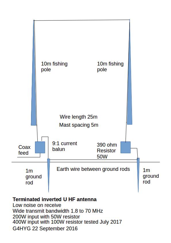
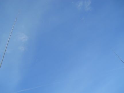
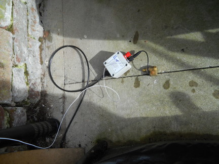
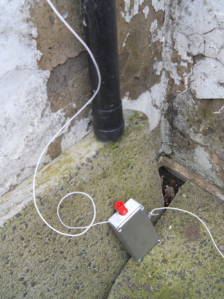
I built the antenna using two 10m fishing poles spaced 5m apart. 25m of thin 7 x 0.2mm insulated wire run up one pole, across to the other then down the other. A 9:1 current balun was used at the feed point with a single 1m ground rod as the earth connection. At the far end a 390 ohm 50W rated thick film resistor was mounted in a diecast aluminium box as heatsink and connected to another 1m ground rod.
Costs are low. The fishing pole antenna supports are readily available, 1m long ground rods are low cost (£5 in the UK from the B&Q hardware store) and Cross Country Wireless can supply the 9:1 current balun and 390 ohm resistor in a box. Well I had to get a plug in somewhere!
In use the VSWR was very low rising to 1.8:1 on 160m and 4m. It's below 1.5:1 on the remaining bands. The receive noise floor is exceptionally low compared to what it was before. The background noise has dropped to very low levels. On 17m and above I have to have the pre-amp switched in to hear the background noise.
On transmit subjectively the performance appears better than the antenna model would suggest. I'm working a lot more stations including DX pileups on 20 and 17m. Maybe the fact I can hear stations properly now that the noise has gone allows me to time my calls better?
In the five days I've had the antenna so far I've worked all over Europe on 160, 80, 40, 60, 30, 20 and 10m, USA on 40, 30, 20 and 17m, Venezuela on 17m, South Africa on 20m and I've had Japanese stations calling me for the first time on 17m. Best of all I've had the strongest reports ever from the local Bolton Wireless Club net on 160m.
Since I designed the antenna I've done an internet search to see if it had been invented before. The closest I could find was the EWE antenna by Floyd Koontz, WA2WVL from QST magazine in 1995. This was a smaller lower version just for 160 and 80m receiving. I've also found a wide range of tactical antennas for miltary use using a similar principle so I'm sure that a similar antenna will have been made years ago.
Conclusions...It's a keeper. I'm building another one for my workshop and I'm selling my ATUs. It's wide band and only uses two short ground rods as an earthing system. For anyone with a small plot for 160m or HF antennas I can't recommend it highly enough especially for it's low noise reception.
Update 5th October 2016.
Since I posted this on the web site and sent it out as a news item it's gone viral and I've had many emails and questions about it. The following are some of the questions I've received with answers.
Does it have to be 10m high or 5m wide or use 25m of wire?... The height can be reduced as low as 5m and still work OK. The 5m spacing in the original design was just to fit in the space I have. 5m is really the minimum and increasing it to 10m, 15m or more will give more gain. The antenna is not resonant (no standing waves) so the wire length is not critical.
Can I run an extra wire between the two earth or ground rods?... I've now tried this and while it increases antenna efficiency by not including the ground rod resistance in the return current path the wire does act as an antenna for local RF noise and a small amount of noise gets back in. If you were to extend the spacing I would recommend that you add extra ground rods along the ground wire to improve the grounding to reduce the noise pickup. I'm going to try that on my antenna to see if it takes it back to the truly quiet noise floor again.
Can I add an extra section to my inverted L antenna to go down to ground via the resistor?... I've been asked this question the most as it's an easy modification for inverted L users. Yes it works and I've had reports back that it's lowered the noise especially on 160 and 80m.
Do I need a 9:1 balun? Can I use my existing remote ATU?... Yes a remote ATU will tune this antenna OK.
Do I need a 9:1 current balun? I already have a 9:1 voltage UnUn... The 9:1 UnUn will match to 450 ohms but it won't add the series impedance to stop common mode RF noise coming down the coax to the antenna. If you use a 9:1 UnUn I suggest you also add a 1:1 current balun as well to stop the common mode noise.
Update 2nd November 2016.
I used this antenna during the CQ WW SSB contest last weekend using 100W from an Icom IC-706 transceiver. The following table shows my results as G4HYG with a score of 46949 points according to the N1MM+ contest logging software:
| Band | QSOs | CQ Zones | Countries |
|---|---|---|---|
| 160m | 2 | 1 | 2 |
| 80m | 44 | 3 | 16 |
| 40m | 35 | 4 | 21 |
| 20m | 148 | 7 | 32 |
| 15m | 66 | 7 | 29 |
| 10m | 8 | 3 | 8 |
| Total | 303 | 25 | 108 |
For me highlights of the contest included contacts with ZD8W in Ascension Island on 15m, CW5W in Chile on 10m and CN2R in Morocco on 80m.
I didn't spend much time on 160m as it's the first time I've ever had a useful antenna on 80m.
I would have made more 160m contacts in the local club net!
I think that it gives a good indication of what is possible with the antenna.
Sometimes you have to get away from the antenna modeling software and make some contacts!
Update 23rd July 2017.
Following useful feedback from Bill, G4CFP I've modified the drawing to add the ground or earth wire between the two ground rods mentioned in the text.
I've also added some information to the drawing about running RF power up to 400W into the antenna. The 9:1 balun is already rated for 400W it needs a 100W resistor for high power use.
Update 19 June 2018.
I've developed a method of using high power wirewound resistors as a RF termination resistor.
The termination resistor we manufacture will now use this method to make a 400 ohm RF load rated at 200W.
Back to main Cross Country Wireless web pages
Contact Chris Moulding, G4HYG via Email address hidden from spambots for more details, comments or feedback.
Click to join cross_country_wireless